Table
of Contents on TuQuick Help
(You may use Ctrl+F or
|
|
Name |
Symbol or expression |
|
addition |
+ |
|
subtraction |
- |
|
multiplication |
*, |
|
division/fraction |
/, |
|
exponentiation |
base^(exponent),
variable’s upper-right superscript |
|
10-base exponentiation |
en, En, where n is an integer |
|
e-base exponentiation |
en, exp(n),
where n is a number |
|
root |
√, root(x;y), sqrt(x) |
|
factorial |
n!, factorial(n) |
|
trigonometric and inverse trigonometric |
sin, cos,
tan, tg, cot, ctg, asin, arcsin, arccos, atan, arctg, atg, actg, acot, arcctg, arccot |
|
hyperbolic functions and inverse hyperbolic
functions |
sinh, cosh, tanh, tgh, coth, ctgh, asinh, arsinh, acosh, arcosh |
|
rounding functions |
Int, round, ceil, floor, frac |
|
logarithmic function |
log, ln, lg |
|
statistical functions |
abs, sgn,
max, min, sum, avg |
|
remainder function |
mod(x;y) |
|
Gamma function |
gamma(x;y) |
|
degree for angle |
n° |
|
convert degrees to radians |
degtorad(x), rad(x) |
|
convert radians to degrees |
radtodeg(x), deg(x) |
|
constant 3.14159… |
π, pi |
|
constant 2.71828… |
e |
|
hexadecimal numbers |
prefix hex number with #,
hex(decimal) |
|
binary numbers |
prefix binary number with &,
bin(decimal) |
|
bit-wise functions |
band, bor,
bxor |
Note:
·
If a function has multiple arguments, these
arguments are separated by “;”.
·
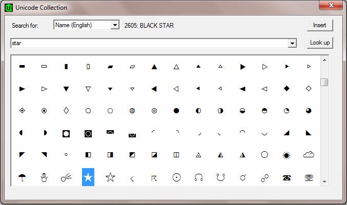
For
how to insert specific symbols or type in math expressions, see topics “2.3 How to insert a symbol?” and “2.4 How to type in mathematical
expressions?”
Examples:
![]()
![]()
![]()
![]()
![]() =
0.904508497187473712051146709
=
0.904508497187473712051146709
acot(sqrt(3)/3) - 60*pi/180 = 0
ceil(-19.99) = -19
log4(123) =
3.471257252669619937309855126
log(123;e) = 4.81218435537241749526200861
max(10;17;13.45) = 17
mod(10.34;-3.2) = 0.74
hex(band(#34;#16)) = #14
To use calculator to get statistics from numbers
in a table:
To undo recent editing actions, use any one of the following
methods:
You can undo many
editing steps you have done in the current editing session. You cannot undo
any editing done prior to opening of this file.
To redo the most recently undone editing actions, use any one of the
following methods:
You can only redo the one or multiple editing steps you have just undone.
To highlight a piece of
content, use any one of the following methods:
Note:
To copy a piece of
content from a TuQuick file to Clipboard, first
highlight the piece, and then use any one of the following methods to complete
the copy:
To cut a piece of
content from a TuQuick file and put it into
Clipboard, first highlight the piece, and then use any one of the following
methods to complete the cut:
To paste the content of
Clipboard (when it is not empty) into a TuQuick
file (at the current caret position), use any one of the following methods to
complete the paste:
Note:
At the end of TuQuick application symbol table, there are a series of Shape buttons in Maroon color (shown
below), which can be used to insert such a basic shape into a file, with the
exception of the last two buttons: “Flood fill” and “Component library”:
![]()
These shape buttons are
called (from left): “Line type”, “Angle type”, “Circle type”, “Triangle
type”, “Quadrilateral type”, “Arc, chord or pie type”, “Pentagon type”,
“Hexagon type”, “Curly draw”, and the last two: “Flood fill” and “Component
library” will be described in later topics. By using simple and easy method
offered by TuQuick, such as clicking buttons, using
hot keys, and/or selecting items from floating menu, a user can change,
color, and/or add text to all the above shapes.
When inserting a shape
into the current file, the shape to be inserted must be within a light grey
rectangle area, called Figure. You
can insert any number of shapes in one figure. Please keep in mind the difference between terms “shape” and “figure”
throughout this entire topic.
Following are few
examples of each shape type.
2.
Examples
of “Angle type”:
3.
Examples
of “Circle type”:
4.
Examples
of “Triangle type”:
5.
Examples
of “Quadrilateral type”:
6.
Examples
of “Arc, chord or pie type”:
7.
Examples
of “Pentagon type”:
8.
Examples
of “Hexagon type”:
9.
Examples
of “Curly draw”:
To insert a new shape in the current file:
By clicking a shape
button (e.g. Triangle type) on top or bottom of the main window, you can
insert a figure at the current caret in your active file, with a basic shape
of the chosen type automatically appearing in the figure (shown below).
A flashing dashed-line
will appear on the bottom of the figure (i.e. the light-gray rectangular
area), indicating that the figure is “selected”; also, a number of small
hollow circles called “Control Points”
will appear on the contour of the shape (in this case, a triangle type
shape), indicating that the shape is also “selected”. By selecting both the
figure and the shape, you can use buttons, combination of shortcut keys
and/or floating menu items to make further adjustment until the basic shape
reaches its final form. You can also click and drag the small green circle
with a dash-lined “tail” to rotate the shape towards any direction centering
this circle.
To insert a new shape in an existing figure:
With an existing figure
select, click a shape button of your choice (e.g. Circle type) on top or
bottom of the main window; the existing figure will enlarge its area to
include the basic form of this new shape (shown below).

Now, only the figure and
the newly-added shape are selected, the original shape is no longer selected,
no matter what its status is prior to the insertion of the new shape. You can
use buttons, combination of shortcut keys, and/or floating menu items to
either adjust the new shape alone, or the relative position between the new
and the old shape until the whole figure reaches its final form.
One thing to keep in
mind is that there are certain caret positions where you are not allowed to
insert any shape, for instance, when the caret is at a special character like , or inside
a table, etc., where all shape buttons will be grayed-out, making them
inactive.
, or inside
a table, etc., where all shape buttons will be grayed-out, making them
inactive.
You must first select
the right “object” before starting to modify a figure or a shape. Following
are a few examples of how to “select” an object, and the opposite operation –
to “de-select” an object.
Method: Move
the mouse to anywhere inside the figure and left click once. A flashing
horizontal dashed-line will appear on the bottom of the light-gray rectangle
area, indicating that the figure is selected, but not the shape.
Method: Move
the mouse to anywhere outside the figure and left click once. The flashing
horizontal dashed-line will disappear on the bottom of the light-gray
rectangle area, indicating that the figure of selection and all the shapes
inside it are de-selected.
Since in a file, no two
or multiple figures can be simultaneously selected, once a figure is
selected, selecting a second figure automatically de-selects the first one.
Method:
Move the mouse to anywhere inside the figure and double-click. A flashing horizontal dashed-line will
appear on the bottom of the light-gray rectangle area; in the meanwhile,
control points will appear on contours of all shapes inside the figure,
indicating that all shapes as well as the figure are selected.
Method:
Move the mouse to anywhere inside the figure where there is no shape and left
click once. All selected shapes will
be de-selected but the figure remains selected.
If you only want to
select one or more, but not all shapes that already exist inside a figure,
choose one of the following two methods:
Method
1:
Position the mouse cursor near the shape you want to select, left click the
mouse when the cursor becomes an arrow shape and points to anywhere on the
contour of the shape (shown below), the shape is thus selected, and so is the
figure where this shape is in (if not already selected); or in the meantime,
other shape(s) are de-selected (if already selected). When the above
procedure is done while pressing the Ctrl key, it allows you to select one
shape at a time, until all shapes are selected, without affecting the status
of selected shapes. This method is similar to the one in Windows environment
where one or more files can be selected simultaneously within a folder.
Method 2: While Shift key is pressed and held down, click the mouse to drag,
and do not release until the shape, or shapes you want to select are
contained in a dash-lined rectangular frame. Shape(s) inside the frame will
all be selected; shapes outside the frame will be de-selected. Again, a shape
will not be selected unless it is completely inside the rectangular frame.
If you only want to
de-select one or more, but not all the shapes that are already selected
inside a figure, use the following method:
Method:
While Ctrl key is pressed down, position the mouse cursor near the shape of
interest, left click the mouse when the cursor becomes ![]() to de-select that shape, regardless of
whether other shapes are selected or not. You can repeat this to de-select
one shape at a time, until all shapes are de-selected.
to de-select that shape, regardless of
whether other shapes are selected or not. You can repeat this to de-select
one shape at a time, until all shapes are de-selected.
Before starting to move,
stretch or rotate a shape, the user must select the target shape.
Next, we show how to
move, stretch or rotate a shape:
Moving:
Whenever there are two or more shapes inside a figure, the user can move a
shape towards any direction, thus to change the original relative position
between the shape moved and the rest of shape(s). This is called moving (or translation, in geometric
term). Moving a shape will not change the type or attribute of the shape. You
cannot move a shape inside a figure if it is the only shape in that figure,
because the relative position is non-existing. A shape can only be moved
within the figure where the shape is in; the figure will automatically resize
to accommodate the translated shape when needed. However, it is not allowed
to move a shape into a different figure.
Method:
Move the cursor around any place other than control points along the contour
of the selected shape until the cursor becomes![]() . Then,
press and hold down the left button on the mouse to drag move the selected
shape to the desired position and then release the button. You can clearly
see where the shape is being moved around with the cursor during this
process.
. Then,
press and hold down the left button on the mouse to drag move the selected
shape to the desired position and then release the button. You can clearly
see where the shape is being moved around with the cursor during this
process.
Sometimes the user needs
to make a very fine position adjustment for a selected shape, or to move a
very tiny shape. In this case, the mouse dragging method above may not be the
best way to achieve the desired effect. A better alternative is to use arrow
keys (up, down, left and right arrow) to move the shape one pixel at a time
so that the object can be fine-tuned to the desired position. Of course, you
also need to select the shape before moving it by arrow keys.
To move multiple shapes
simultaneously, just select all of them, and then apply the same method
above.
Stretching: When the user needs to modify an existing shape for whatever
reason, for instance, to make a triangle from right to oblique; or to change an ellipse from rounder to leaner,
etc., all of such shape manipulations are called stretching.
Method:
Move the cursor around a control points along the contour of the selected
shape until it becomes![]() . Then,
press and hold down the left button on the mouse to drag move the control
point to its desired new position so that the shape can be stretched
accordingly. You can see how the shape is being stretched during the entire
dragging. Release the button when the shape is stretched to the desired form.
The figure will automatically resize to accommodate the stretched shape when
needed.
. Then,
press and hold down the left button on the mouse to drag move the control
point to its desired new position so that the shape can be stretched
accordingly. You can see how the shape is being stretched during the entire
dragging. Release the button when the shape is stretched to the desired form.
The figure will automatically resize to accommodate the stretched shape when
needed.
Rotating: When the rotation handle (a green little circle with a dash-lined
tail) appears with the selected shape, it means that the shape can be rotated
towards any intended orientation.
Method:
When the rotation handle appears with the shape, and the cursor becomes![]() around that
indicator, press and hold down the left button on the mouse to drag rotate
the selected shape to change its orientation. You can see how the shape’s
orientation is being changed during the entire dragging. Release the button
when the shape is rotated to the desired orientation. The figure will
automatically resize to accommodate the rotated shape when needed.
around that
indicator, press and hold down the left button on the mouse to drag rotate
the selected shape to change its orientation. You can see how the shape’s
orientation is being changed during the entire dragging. Release the button
when the shape is rotated to the desired orientation. The figure will
automatically resize to accommodate the rotated shape when needed.
One thing to mention is
that sometimes there is no such rotation handle for a selected ellipse (e.g.
right after it is inserted). Why? We will explain later.
Tips for stretching a shape with its end point
perfectly touching another: Highlight
the two shapes crossing each other, then right click and select “Cut extra”
menu on the corresponding end point to cut extra line segment. See below.
![]()
![]()
Tips for stretching out of file window: When a figure is close to a border of a file
window, your stretching may be blocked by the file window border. To help
extend your stretching further in this case, use menu “View”=> “Add Fig
Frame”.
Tips for using “Move point to…” to stretch line
segments: Right click on a point
of a line segment, select “Move point to…” menu, then enter or select an
angle and a length to move the point to a desired location. Following the
example below to operate, you can draw a very regular five-start shape.
![]()
![]()
![]()
![]()
![]()
![]()
![]()
![]() Repeat the last step exactly for the next three
points.
Repeat the last step exactly for the next three
points. ![]()
![]()
![]()
Whether you want to cut,
copy, paste or delete a whole figure (including the figure and all shapes in
the figure), or just to cut, paste, copy or delete a shape or a few shapes in
a figure, you must first select the right item(s) and then take one of the
following operations.
Following are
definitions and methods of cut, copy, paste and delete.
Cut:
Copy the selected shape (or figure) to the ClipBoard,
and delete it at the same time.
Copy: Copy
the selected shape (or figure) to the ClipBoard.
Paste: Insert
the content from the ClipBoard to where the caret
is.
Delete: Delete
the selected shape (or figure).
Once you have selected a
shape, you can modify its attributes by right-clicking on the shape contour
to select a command from a floating menu. Command options available from a
floating menu differ from shape to shape, and whether your mouse cursor is at
a point (control point) or on a line (non-control point). It is summarized as
below:
|
|
Move
cursor to any control point |
Move
cursor to anywhere other than control points |
|
Cursor becomes: |
|
|
|
Shape attributes to be
modified: |
Geometric
characteristics of the shape: e.g. angle degree, orientation, etc. |
Line features of the
shape: e.g. color, arrow-ended, thickness, grid, etc. |
Note:
Following a few examples
explain how a floating menu command works in more detail:
Angle types: “Equal rays” command
Select this floating
menu command to assign attribute “equal length” to the two rays that form an
angel, i.e. when you drag one ray from its end to extend (or shorten) its
length, the other ray will be extended (or shortened) to the same length. To
revoke this attribute, simply select “Any rays” command from the same
floating menu. Commands “Equal rays” and “Any rays” work in such a way that
when one of them is active, the other one will appear in the same menu.
Circle types:
Click the “Circle type”
button from either the top or bottom Toolbar to insert a circle type shape.
The first circle shape inserted in your figure is always going to be an
ellipse; you can drag any control point to change its shape.
·
Circle types: “Fixed aspect ratio”
command
Select this floating
menu command to assign attribute “keeping the current ratio of major and minor semi-axes” to the ellipse. You can still drag a control
point to change its size, but you can not change its aspect ratio. To revoke
this attribute, simply select “Any ellipse” command from the floating menu,
which removes any constrain of size, ratio and/or elongation of the ellipse.
Commands “Fixed aspect ratio” and “Any ellipse” work in such a way that if
one of them is active, the other one will appear in the same floating menu.
·
Circle types: “Any orientation”
command
Select this floating
menu command to assign attribute “rotating to any orientation” to the
ellipse, and enable a green rotation handle (See topic “2.12 How to move, stretch or
rotate a shape?”). When the cursor becomes![]() around the
indicator, you can press and hold down the left button on the mouse to
drag-rotate the selected shape to change its orientation. You can see how the
shape’s orientation is being changed during the entire dragging process.
Release the button when the shape is rotated to the desired orientation. The
figure will automatically resize to accommodate the rotated shape when
needed. When “
around the
indicator, you can press and hold down the left button on the mouse to
drag-rotate the selected shape to change its orientation. You can see how the
shape’s orientation is being changed during the entire dragging process.
Release the button when the shape is rotated to the desired orientation. The
figure will automatically resize to accommodate the rotated shape when
needed. When “
Triangle types:
Click the “Triangle
type” button from either the top or bottom Toolbar to insert a triangle type
shape. The first triangle shape inserted in your figure is always going to be
a right triangle; you can drag any control point to change its shape.
·
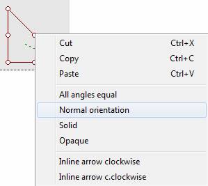
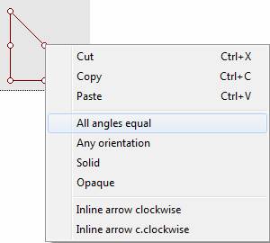
Triangle types: “Two angles equal”
command
When this floating menu
command is selected from the floating menu at vertex A, it instantly changes
the original triangle to an isosceles triangle, i.e. two sides are equal in
length from A. You can drag the triangle from any of the three vertices to
change its shape, but until you select command “Any degree” from the same
floating menu, the attribute “two sides are equal in length from vertex A” will persist. When you select “Any degree”
command, you will not see an instant change of the shape; however, when you
drag the triangle from a vertex, the attribute “two sides are equal in
length” no longer holds, therefore, the length of each side from that vertex
can be changed arbitrarily.
Quadrilateral types:
Click the “Quadrilateral
type” button from either the top or bottom Toolbar to insert a quadrilateral
type shape. The first quadrilateral shape inserted in your figure is always
going to be a rectangle; you can drag the shape from any control point to change
its length and width. You may right-click on any control point to change the
attribute from rectangle to other quadrilateral from the floating menu.
·
Quadrilateral types: “Trapezoid”
command
When this command is
selected, you will not see an instant change to your original shape; however, once you start dragging one or two
vertex from its four vertices, you can make the original shape become a
trapezoid; and during the dragging, the attribute
“a parallelogram
with at least one pair of parallel opposite sides” will persist, unless you
select another command from the same floating menu to change it.
·
Quadrilateral types: “Small grid”
command
If the shape inserted is
a rectangle or a square, and attribute “Normal orientation” is active, then
in the floating menu from any non-control point on the contour of the shape,
you will find commands “Small grid”, “Medium grid” and “Large grid”. You can select any
of these commands to enable a grid inside the rectangle or the square, to be
used as a kind of coordinate system for making your further drawing easier.
You may select “No grid” when you are done drawing.
·
All closed-shape types:
“Transparent”, “Solid”, “Opaque” command
The oval shapes in the
following figure illustrate the effect of each of these three commands
respectively.
We will not go into details here for other floating menus, as users are
expected to master easily by playing them, with the help from the
self-explanatory hint provided in the status bar (at the bottom of the main
window).
You can change the color
of a shape (“Maroon” being the default shape color) using one of the two
methods (they will have different coloring effects); or a combination of
both, as described below:
1)
Select
a shape.
2)
Place
cursor over any place other than control points along the contour of the
selected shape until the cursor turns to![]() . Right
click on the cursor to select a color from floating menu “Shape colors…”.
. Right
click on the cursor to select a color from floating menu “Shape colors…”.
3)
If
the shape is enclosed, you may use floating menu “Solid” to fill the shape
interior with the same color as on its line(s).
1)
Select
a figure.
2)
Click
“Flood fill” button ![]() from either
top or bottom Toolbar, an arbitrary area in the figure will be filled with an
arbitrary color. A “Flood fill” indicator with the same color will appear,
indicating that the flood filling status is “selected” and its attribute can
be modified.
from either
top or bottom Toolbar, an arbitrary area in the figure will be filled with an
arbitrary color. A “Flood fill” indicator with the same color will appear,
indicating that the flood filling status is “selected” and its attribute can
be modified.
3)
Place
your mouse over the “Flood fill” indicator until it becomes![]() . Press and drag the indicator to your
desired area, and release the mouse button to fill.
. Press and drag the indicator to your
desired area, and release the mouse button to fill.
4)
To
change to a different color, right click at the indicator and select the color
of your choice from the floating menu.
5)
When
“Flood fill” is not “selected”, clicking anywhere in its colored area can
make it “selected”.
Difference
between two coloring methods
|
|
Floating menu “Shape colors…” |
“Flood fill” |
|
Coloring area |
Lines, and interior
when “Solid” is selected, within one shape |
Transparent area
between any lines (regardless of one or multiple shapes) |
|
Edit-ability
(copy/cut/paste/move) |
The color always goes
with the shape it is applied to |
“Flood fill” is an independent
object, thus has its own copy/cut/paste/move just like any shape |
|
Number of color
choices |
14 |
20 (14 colors, 6 hatched lines) |
You may use either one
or both methods, to add or modify your shape color, depending on your
applications. Topic “2.19
Could you show me a few examples on how to draw figures and shapes?”
gives some examples of how to add or change color(s) to shapes.
A shape component is a
group of at least two shapes which are together when performing following
operations: copy, cut, paste, delete, drag move, rotate, scale and flip (flip
operation does not exist for single shape but exists for a shape component).
To compose a new component:
Note: text or image
inside a figure cannot be a part of a component.
To decompose an existing component:
To rotate a component:

Note: A component cannot
be rotated if any of its member shapes cannot be rotated.
To scale a component:
To flip a component:
TuQuick software comes with a set of shape component libraries, allowing
you to copy/paste some useful shape components. To open shape component
library, click button: ![]() . You then click a category line to load
shape components in that category. Must recently used
25 shape components are automatically kept in the first category
“00_Most_Recent” for your convenience. You may use the same method as in “2.21 How to find or replace text
string?” to find a shape component’s name in these libraries.
. You then click a category line to load
shape components in that category. Must recently used
25 shape components are automatically kept in the first category
“00_Most_Recent” for your convenience. You may use the same method as in “2.21 How to find or replace text
string?” to find a shape component’s name in these libraries.
You can make your own
shape component libraries. You can also share your shape component libraries
with others by uploading them as TuQuick solutions.
To insert an image into
your TuQuick file, first move the caret to where
you want the image to be inserted, then use any one of the following methods:
1)
Click
menu “Edit” => “Import” =>
“Image”.
2)
Browse
to the image(s) you want to insert.
3)
Double-click
or select the image(s) then click “Open” to insert.
Note:
·
You
may select a particular type of image file to insert, or simply use “All
supported image files”, from the pull-down menu.
·
You
can insert maximum 8 images at a time using this method.
1)
From
a WORD document file, highlight image(s) (possibly including text at the same
time). Copy.
2)
Go
back to your TuQuick file. Paste.
1)
Once
interested area is displayed on your screen (e.g. a web page), press PrtSc key to capture the entire screen (or press Alt+PrtSc key to capture the currently selected window).
At this point, copy is done.
2)
Go
back to your TuQuick file. Paste. A dialog box
containing the captured screen will open.
3)
Use
left mouse button to drag and select a region of interest in the dialog box.
(Use Ctrl+A key to select all, which is also the
default.)
4)
Press
Enter. The selected image content will be inserted to where the caret is in
your TuQuick file.
Note: In all of the
above:
1.
When
a figure or a shape/image inside the figure is selected, click “Insert
special text” button ![]() from the Toolbar (or press shortcut keys Alt+E, then S) and then move the mouse cursor to inside
the figure. The cursor will then turn into a textbox cursor
from the Toolbar (or press shortcut keys Alt+E, then S) and then move the mouse cursor to inside
the figure. The cursor will then turn into a textbox cursor![]() .
.
2.
Move
the textbox cursor until the pencil tip is pointing to the position where you
want to insert text; click; a small yellow rectangular textbox appears with a
blue caret flashing, indicating it is OK to enter text (including symbols,
superscript and/or subscript, etc.)
3.
Type
text in the textbox the same way you normally do, except there is no auto
wrapping. The size of a textbox will automatically increase to accommodate
the text entered. Hit “Enter” to wrap.
1.
Click
to select the desired textbox.
2.
Modify
the text within the textbox in the same way as in normal text area (change of
text color and all copy/cut/paste/move operations are supported).
1.
To
move one or multiple textbox(es):
![]() To
move a textbox, select the textbox, place the mouse to the border of the
textbox until the cursor becomes
To
move a textbox, select the textbox, place the mouse to the border of the
textbox until the cursor becomes![]() , then click
the mouse to drag the textbox to a desired new location.
, then click
the mouse to drag the textbox to a desired new location.
![]() To
fine-tune a textbox’s location, select the textbox, press Shift+ArrowKey
(up, down, left or right) to move it slightly in one direction. Holding down
the above key combination to continuously do so.
To
fine-tune a textbox’s location, select the textbox, press Shift+ArrowKey
(up, down, left or right) to move it slightly in one direction. Holding down
the above key combination to continuously do so.
![]() To
move multiple textboxes as a whole within the same figure, select these
textboxes, place the mouse to the border of any textbox until the cursor
becomes
To
move multiple textboxes as a whole within the same figure, select these
textboxes, place the mouse to the border of any textbox until the cursor
becomes![]() , then click
the mouse to drag all selected textboxes to a desired new location. The
figure will automatically change its size to accommodate the textbox move.
(This works the same way as moving multiple shapes in a figure. See topic 2.12 How to move, stretch or
rotate a shape?)
, then click
the mouse to drag all selected textboxes to a desired new location. The
figure will automatically change its size to accommodate the textbox move.
(This works the same way as moving multiple shapes in a figure. See topic 2.12 How to move, stretch or
rotate a shape?)
![]() Similarly,
you can fine-tune multiple textboxes to a desired location by selecting the
textboxes and using arrow keys to move them slightly until they are at the
desired location.
Similarly,
you can fine-tune multiple textboxes to a desired location by selecting the
textboxes and using arrow keys to move them slightly until they are at the
desired location.
2.
To
change any of these textbox attributes - font size, font face, font style, or
background transparency, place the mouse to border of the textbox until the
cursor becomes![]() , then
right-clicking to select an appropriate option from the floating menu. Topic
“2.19 Could you show me a few
examples on how to draw figures and shapes?” gives some examples of how
to edit your textbox.
, then
right-clicking to select an appropriate option from the floating menu. Topic
“2.19 Could you show me a few
examples on how to draw figures and shapes?” gives some examples of how
to edit your textbox.
3.
As
you copy/cut one or multiple textbox(es), make sure that you have selected the textbox(es) without selecting any text inside.
Note: Using textboxes
can meet needs of some special text expressions. The following is an example
(manually do division).
Sure. In the following
examples, we are going to show you and explain to you how to draw figures,
and further more, to better understand the use of floating menus.
Example 1 Let’s illustrate how to draw the following 3D shape with two
methods:
Method 1. Consider this shape as two separate rectangular planes (in front and
back) connected by four equal-length line segments, and one angle.
(1)
Click
the “Quadrilateral type” button ![]() from either the top or bottom Toolbar to
insert a rectangle.
from either the top or bottom Toolbar to
insert a rectangle.
(2)
Place
the cursor over control point at bottom right corner (the cursor will become![]() ). While
pressing down the left button, drag the rectangle until the right ratio of
length vs. width is reached (the cursor becomes
). While
pressing down the left button, drag the rectangle until the right ratio of
length vs. width is reached (the cursor becomes![]() during
moving). (Note that dragging a non-control point will only change the length
of one set of opposite side.)
during
moving). (Note that dragging a non-control point will only change the length
of one set of opposite side.)
(3)
“Copy”/“Paste”
and move the rectangle by placing the cursor over any non-control point when
it becomes![]() , then press
the left button to drag:
, then press
the left button to drag:
(1)
Click
the “Line type” button ![]() from either the top or bottom Toolbar to
insert a line.
from either the top or bottom Toolbar to
insert a line.
(2)
Move
one end of the line segment using the same way in 1–(2), to connect it to one
plane. Do the same to connect the other end to the second plane. When
finished, the line segment is selected and its length is fixed. Re-select and
move the planes until satisfied with the relative position between the line
segment and the planes:
(3)
You
can add other three line segments by using “Copy”, “Paste” and Move. However,
when a line segment is pasted, it remains selected, and the original line
segment is automatically de-selected. Since pasted lines are overlapped on
top of one another, therefore, you may move the pasted line to a new position
before pasting next one, as illustrated by the following flow of figures:
![]()
![]()
![]()
(1)
Click
the “Angle type” button ![]() from either the top or bottom Toolbar to
insert an angle;
from either the top or bottom Toolbar to
insert an angle;
(2)
Referring
the figure below, drag-move each of the three end-points to its ideal
location, one line connecting points A and B, the other line connecting
diagonal points of bottom quadrilateral, forming a “look-like” right
triangle.
(3)
When
cursor is placed over the vertical line segment of the right triangle, select
floating menu “Thick line”.
(4)
When
cursor is placed over either of the two lines of the angle shape, select
floating menu “Thick line(s)”, to form a thick line triangle:
(1)
Click
“Insert special text” button ![]() from the Toolbar. The mouse cursor becomes
textbox cursor
from the Toolbar. The mouse cursor becomes
textbox cursor ![]() when it is
inside the figure. Move the textbox cursor until the pencil tip is pointing
to a position where the text will be inserted; click the left mouse button, a
small yellow rectangular textbox appears with a blue caret flashing,
indicating it is waiting for you to enter the text. Entering text inside a
figure works the same way as entering normal text:
when it is
inside the figure. Move the textbox cursor until the pencil tip is pointing
to a position where the text will be inserted; click the left mouse button, a
small yellow rectangular textbox appears with a blue caret flashing,
indicating it is waiting for you to enter the text. Entering text inside a
figure works the same way as entering normal text:
(2)
Enter
number “4”. The textbox will automatically increase its size to accommodate
more characters if needed.
Since clicking “Insert special
text” button once only inserts text to one place, therefore, you need to
repeat the above steps until all text are entered in all locations.
If not satisfied with
the location the text was entered, you can select the text by clicking it
again to make the textbox appear, then press and hold down the left button
when the cursor becomes![]() at the
textbox frame to drag the text along with the textbox to a better location.
at the
textbox frame to drag the text along with the textbox to a better location.
Follow these steps to
insert “![]() ”: Click
”: Click ![]() from the Toolbar, move the cursor to somewhere
near the triangle and click, a yellow textbox will appear; click “
from the Toolbar, move the cursor to somewhere
near the triangle and click, a yellow textbox will appear; click “![]() ” from
either the top or bottom Toolbar to insert a square-root, then click
” from
either the top or bottom Toolbar to insert a square-root, then click ![]() again
and click inside the square-root “
again
and click inside the square-root “![]() ”, enter
“65” at the yellow textbox inside “
”, enter
“65” at the yellow textbox inside “![]() ”, done. You
may review the contents in topic “2.4 How to type in mathematical
expressions?” for more details.
”, done. You
may review the contents in topic “2.4 How to type in mathematical
expressions?” for more details.
Method 2. Consider this shape as two separate quadrilateral planes (one on top
of another) connected by four equal-length vertical line segments, and two
sides that form the triangle.
(1)
Click
the “Quadrilateral type” button from either the top or bottom Toolbar to
insert a rectangle.
(2)
Move
the cursor over any control point; press the right button and select
“Parallelogram” from the floating menu.
Press the left button on a control point from any of the four vertexes
and drag to change the shape from a rectangle to a parallelogram.
(3)
Press
the left button at control point of the vertex to change the length/width
ratio of the parallelogram. (Note that the parallelogram is active at this
moment).
(4)
“Copy”/“Paste”
and move the second parallelogram by placing the cursor over any non-control
point when it becomes![]() , then press
the left button to drag:
, then press
the left button to drag:
(1)
Click
the “Line type” button from either the top or bottom Toolbar to insert a
line.
(2)
Place
the cursor over any non-control point on the line and click the right button.
Select “Vertical line” from the floating menu (the line will maintain its
vertical status no matter how you move it).
(3)
Move
the vertical line so that one of its ends touches one of the four vertexes of
the top parallelogram plane.
(4)
Place
the cursor over the other end of the vertical line until it become![]() , press the
left button so that the cursor becomes
, press the
left button so that the cursor becomes![]() , and drag
to extend the length of the vertical line like this:
, and drag
to extend the length of the vertical line like this:
(5)
Select
the bottom plane again and move it to the right position:
(6)
Use
“Copy”, “Paste” , and move, to add other three line segments, the same way as
in 2-(3) of Method 1:
![]()
(1)
We
can use the first line segment that connects the two planes as one side of
the triangle, and insert two more straight lines and move their respective
ends to the right places:
![]()
(2)
While
pressing down the Ctrl key, place the mouse around any one of the three lines
of the triangle. When the cursor becomes![]() , click the
mouse to select that line. Repeat this on other two lines until all three
lines are selected:
, click the
mouse to select that line. Repeat this on other two lines until all three
lines are selected:
(3)
At
any non-control point of any side, click the right button, select “Thick
line(s)” from the floating menu:
Example 2 Let’s illustrate how to draw the following geometric figure:
1.
Draw
a circle:
(1)
Click
the “Circle type” button ![]() from either the top or bottom Toolbar to insert a
circle:
from either the top or bottom Toolbar to insert a
circle:
(2)
Place
the cursor over a control point on the circle (the cursor becomes![]() ). Click the
right button. Select “Circle” from the floating menu to force the oval shape
to be a circle.
). Click the
right button. Select “Circle” from the floating menu to force the oval shape
to be a circle.
(3)
Place
the cursor over a control point on the circle (the cursor becomes![]() ). Click the
right button. Select “Show center” from the floating menu.
). Click the
right button. Select “Show center” from the floating menu.
(4)
Place
the cursor over a control point on the circle (the cursor becomes![]() ) and click
the left button (the cursor becomes
) and click
the left button (the cursor becomes![]() ). While
holding down the left button, drag that point to enlarge the circle size:
). While
holding down the left button, drag that point to enlarge the circle size:
(1)
Click
the “Line type” button ![]() from either the top or bottom Toolbar to insert a
line.
from either the top or bottom Toolbar to insert a
line.
(2)
Place
the cursor over any non-control point on the line (the cursor becomes![]() ). Click the
right button. Select “Horizontal line” from the floating menu. The line will
maintain its horizontal status no matter how you move it:
). Click the
right button. Select “Horizontal line” from the floating menu. The line will
maintain its horizontal status no matter how you move it:
(3)
Place
the cursor over an end-point on the line (the cursor becomes![]() ) and click
the left button (the cursor becomes
) and click
the left button (the cursor becomes![]() ). While
holding down the left button, drag that point to extend length of the
horizontal line.
). While
holding down the left button, drag that point to extend length of the
horizontal line.
(4)
Place
the cursor over any non-control point on the line (the cursor becomes![]() ). While
holding down the left button, drag the horizontal line towards the center of the
circle:
). While
holding down the left button, drag the horizontal line towards the center of the
circle:
(5)
Repeat
steps (1) to (4) except to select “Vertical line” from the floating menu:
(6)
Select
one line at a time. Use “Up”/“Down” and “Left”/”Right” arrow keys
respectively, to fine-adjust the two lines so that they are perpendicular
each other and across at the circle center:
3.
Draw
lines OFG and EF:
From the example we can
see that line OFG consists of a solid-line segment (EF) and a dashed-line
segment (FG). This can be done by inserting an angle and modify it using a command
from floating menu. Here is how:
(1)
Click
the “Angle type” button![]() from either the top or bottom Toolbar to
insert an angle. Place the cursor over non-control point on the angle (the
cursor becomes
from either the top or bottom Toolbar to
insert an angle. Place the cursor over non-control point on the angle (the
cursor becomes![]() ). While
holding down the left button, drag the angle’s vertex to the proper position
of the circle. Use arrow key to fine-adjust:
). While
holding down the left button, drag the angle’s vertex to the proper position
of the circle. Use arrow key to fine-adjust:
(2)
Place
the cursor over a non-vertex control point on the angle (the cursor becomes![]() ). While
holding down the left button, drag that point until it touches the center of
the circle. Use arrow key to fine-adjust:
). While
holding down the left button, drag that point until it touches the center of
the circle. Use arrow key to fine-adjust:
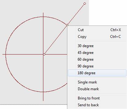
(3)
Place
the cursor over the vertex (the cursor becomes![]() ). Click the
right button and select “180 degree” from the floating menu. The three
control points are now lined-up and remain one straight line, no matter how
you move it:
). Click the
right button and select “180 degree” from the floating menu. The three
control points are now lined-up and remain one straight line, no matter how
you move it:
![]()
(4)
Place
the cursor over the line segment outside the circle (the cursor becomes![]() ). Click the
right button and select “Dashed line” from the floating menu:
). Click the
right button and select “Dashed line” from the floating menu:
(5)
Click
the “Line type” button ![]() from either the
top or bottom Toolbar to insert a line. Place the cursor over non-control
point on the line (the cursor becomes
from either the
top or bottom Toolbar to insert a line. Place the cursor over non-control
point on the line (the cursor becomes![]() ). Select
“Vertical line” from the floating menu. The line will maintain its vertical
status no matter how you move it.
). Select
“Vertical line” from the floating menu. The line will maintain its vertical
status no matter how you move it.
(6)
Place
the cursor over the line’s non-control point (the cursor becomes![]() ). While
holding down the left button, drag the line to the right place:
). While
holding down the left button, drag the line to the right place:
Since angle EFG consists of two independent shapes – a line type and an angle type, we can not use “Single mark” command from the floating menu for the angle type, rather, we would use “Angle arc” command, as described below:
(1)
Click
to select line EF. Press down Ctrl key to select line OFG using the same
method. Thus both lines are selected.
(2)
Place
the cursor between line EF and dashed-line FG. Click the right button, and
select “Angle arc” command from the floating menu (When doing so: (a) EF and
FG must touch at point F; (b) the point location of the right click
determines the radius of the angle arc; (c) that radius is not allowed to be
too small.):
Example 3 Let’s illustrate how to apply different coloring features to draw
the following RGB color model:
1.
Draw
an equiangular triangle as auxiliary to help make sure that all three circles
are symmetric to one another:
(1)
Click
the “Triangle type” button![]() from either
the top or bottom Toolbar to insert a triangle.
from either
the top or bottom Toolbar to insert a triangle.
(2)
Place
the cursor over any control point on the triangle (the cursor becomes![]() ). Click the
right button and select “
). Click the
right button and select “
(3)
Place
the cursor over any control point on the triangle (the cursor becomes![]() ). Click the
right button and select “All angles are equal” from the floating menu. This
is to make the triangle equiangular.
). Click the
right button and select “All angles are equal” from the floating menu. This
is to make the triangle equiangular.
(4)
Place
the cursor over any control point on the equiangular triangle (the cursor
becomes![]() ). While
holding down the left button, drag the point to enlarge the triangle to a
size such that the length of each side approximately equals to the distance
between any two circle centers.
). While
holding down the left button, drag the point to enlarge the triangle to a
size such that the length of each side approximately equals to the distance
between any two circle centers.
![]()
![]()
![]()
2.
Draw
a red circle:
(1)
Draw
a circle in the same way as described in Example 2 with “Show center” option
turned on.
(2)
Change
the circle size to the desired size in the same way as described in Example
2.
(3)
Place
the cursor over a non-control point on the circle (the cursor becomes![]() ). Click the
right button and select “Shape colors…” from the floating menu. From the
menu, click “Red” to change the color of the line from “Maroon” (the default
color) to “Red”.
). Click the
right button and select “Shape colors…” from the floating menu. From the
menu, click “Red” to change the color of the line from “Maroon” (the default
color) to “Red”.
(4)
Place
the cursor over a non-control point on the circle (the cursor becomes![]() ). Click the
right button and select “Solid” from the floating menu.
). Click the
right button and select “Solid” from the floating menu.
![]()
![]()
![]()
![]()
3.
Apply
shape editing to complete the green and blue circles:
(1)
Select
the red circle to copy and paste, and then change its color to “Green” by
using the “Shape colors…” floating menu. Move the green circle to aside (so
that it does not overlap with the circle to be pasted next):
(2)
Repeat
the above steps to get the blue circle:
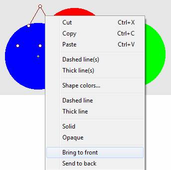
4.
Move
three circles to their proper location with the help of the aux triangle:
(1)
Bring
the aux triangle to the front of the figure:
a.
Click
to select the auxiliary triangle.
b.
Place
the cursor over a non-control point (the cursor becomes![]() ).
).
c.
Click
the right button and select “Bring to front” from the floating menu:
![]()

(2)
Individually
select to move each circle until its center is aligned with the respective
angle of the triangle (Use arrow keys to find-adjust if necessary):
(3)
Select
the triangle to delete. Then, for every circle, remove circle center by
selecting option “Not show center”:

5.
So
far we have illustrated how to apply “Shape colors…” method. This method,
however, is unable to fill colors in irregular areas, for instance, areas
overlapped by shapes, or background. In the next, we will show how to achieve
this by using the “Flood fill” method:
(1)
Continuing
from previous point, click to select one circle (e.g. blue).
(2)
Remove
the interior color by clicking the right button when the cursor is over a
non-control point on the circle (the cursor becomes![]() ), and
select “Transparent” from the floating menu:
), and
select “Transparent” from the floating menu:
![]()
(3)
Repeat
the above steps to remove the interior colors for the red and green circles:
(4)
Select
the figure. Click the “Flood fill” button ![]() from either
the top or bottom Toolbar. A “Flood fill” indicator with an arbitrary color
appears in the figure:
from either
the top or bottom Toolbar. A “Flood fill” indicator with an arbitrary color
appears in the figure:
(5)
Move
the indicator to a desired area and then right click on the indicator to show
the color menu. Choose a color intended for this area to fill (e.g. “Red”):
![]()
(6)
Copy
the “Flood fill” indicator and paste it seven times (six areas on the circles
and one area on the background). After each paste, first move the pasted “Flood
fill” indicator to one of the unfilled areas, then modify its color as
required:
6.
Finally,
add text:
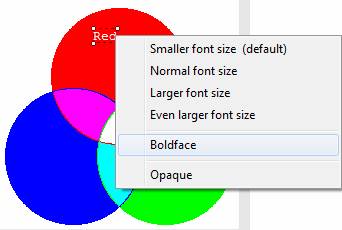
(1)
Insert
a textbox in the red circle (Refer to step 4 of Method 1 in Example 1). Right
click at the caret to select option “Text colors…” from the floating menu.
Set textbox color to an easy-to-see color, e.g. “White” for “Red”. Type
“Red”.
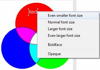
(2)
Move
your mouse to the border of the textbox until the cursor becomes![]() . Right
click on border of the textbox to select option “Even smaller font size” from
the floating menu.
. Right
click on border of the textbox to select option “Even smaller font size” from
the floating menu.
(3)
Repeat
the above to select option “Boldface” from the floating menu.
(4)
Move
your mouse to border of the textbox until the cursor becomes![]() . Click the
mouse to drag the textbox to a desired new location.
. Click the
mouse to drag the textbox to a desired new location.
![]()
![]()
![]()
(5)
Similarly,
repeat the above steps to enter text in other areas:
Example 4 Let’s illustrate how to draw the following sine wave with
coordination:
1.
Insert
a rectangle as drawing reference:
(1)
Click
the “Quadrilateral type” button![]() from either
the top or bottom Toolbar to insert a rectangle.
from either
the top or bottom Toolbar to insert a rectangle.
(2)
Press
the left button on the control point at the lower-right corner and drag to increase
size of the shape, release the button when it is big enough (You may continue
to increase the size later during the whole drawing process when needed).
2.
Add
grid to help it easier to coordinate:
(1)
Move
cursor on any control point and click the right button. Select “
(2)
Under
normal orientation, place the cursor over any non-control point and click the
right button. This time, select “Medium grid” from the new floating menu:
3.
Draw
coordination:
(1)
Click
the “Line type” button![]() from either
the top or bottom Toolbar to insert a line.
from either
the top or bottom Toolbar to insert a line.
(2)
Place
the cursor over any non-control point on the line and click the right button.
Select “Horizontal line” from the floating menu.
(3)
Drag
an end-point to extend the line.
(4)
Place
the cursor over the right end-point of the line and click right button to
select “Arrow end”.
(5)
Place
the cursor over any non-control point on the line and click the right button
to select “Medium scale mark” (to match the medium grid).
(6)
Place
the cursor over any non-control point on the line, press the left button to
drag the line to its proper position.
So
far we have drawn the horizontal axe of the coordination. Repeat the above to
draw the vertical axe.
4.
Add
text for the coordination (Refer to Example 1, step 4):
(1)
Click
button![]() . Move the
mouse cursor
. Move the
mouse cursor![]() to near the
top of the vertical axis, and then click to enter “Y” at the textbox caret.
to near the
top of the vertical axis, and then click to enter “Y” at the textbox caret.
(2)
Similarly,
enter 5, 4, 3, 2, 1, 0, -1, -2, -3, -4, and -5, for the scale marks of Y
axis.
(3)
Similarly,
enter “![]() (radians)”,
and
(radians)”,
and ![]() for the horizontal axis and its scale marks,
respectively.
for the horizontal axis and its scale marks,
respectively.
Note:
Method used to enter fraction in a textbox is the same as for regular text.
(See Example 3: Insert fraction by both mouse and keyboard from topic “2.4 How to type in mathematical
expressions?”). If still not satisfied with the text position, you can
move the whole text part by placing the cursor over the textbox until it
becomes![]() , then press
and hold the left button to drag.
, then press
and hold the left button to drag.
5.
Draw
a unit shape, then use combination of copy/paste/rotate/move to finish the
entire solid-line graph:
(1)
Select
the figure. Click the “Curly draw” button ![]() from either the top or bottom Toolbar to
insert a curly line.
from either the top or bottom Toolbar to
insert a curly line.
(2)
Move
control points on the shape to change the shape:
(3)
Properly
adjust the unit shape by moving each of the control points towards the ideal
shape:
(4)
Select
the unit shape, then use copy/paste to add a new unit shape (with the second one
selected).
(5)
Move
the second unit shape away from the first one. Place the cursor near the
green rotation handle until the cursor becomes![]() . Rotate the
second shape by 180 degree:
. Rotate the
second shape by 180 degree:
(6)
Move
the second unit shape so that it continues from the first one, nicely and
smoothly.
(7)
Press
down the Ctrl key to select unit shape one and then two, then copy, paste and
move both shapes to the new position:
Now
we have completed the entire solid-line graph.
6.
It
is much easier to draw the dashed-line graph:
(1)
Press
down the Ctrl key to individually select all four unit shapes, then copy and
paste. Move the copied graph away from the original one.
(2)
Place
the cursor over the second graph and click the right button to select “Dashed
line(s)” from the floating menu.
(3)
Move
the entire dashed-line graph towards ![]() /3 to the
right of the solid-line graph:
/3 to the
right of the solid-line graph:
7.
To
finish some details:
(1)
Use
copy, paste and move to extend the left side of the dashed-line graph by the
length of one unit shape.
(2)
Place
the cursor over the left-most control point of the dashed-line graph and
click the right button. Select “Remove node” from the floating menu to remove
the left-most control point, thus to delete the excessive part of the
dashed-line graph.
(3)
Click
the “Insert special text” button to insert math equation “y=5sin![]() ” next to
the solid-line graph (“
” next to
the solid-line graph (“![]() ” can be
selected from either the top or bottom Toolbar). Insert “y=5sin (
” can be
selected from either the top or bottom Toolbar). Insert “y=5sin (![]() -
-![]() /3)” for the
dashed-line graph.
/3)” for the
dashed-line graph.
(4)
We
realize the X axe can be a little bit longer. So we select the line to extend
it. Also select the textbox to move “![]() ” towards
the right end of the line:
” towards
the right end of the line:
(5)
Finally,
we need to remove the auxiliary references. Select the rectangle that we
introduced at the beginning. Click “No grid” from the floating menu to
deselect the grid, then click Delete key to remove the rectangle. Now we have
completed this figure as shown in the example:
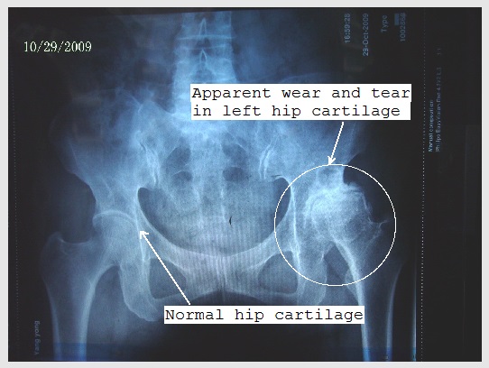
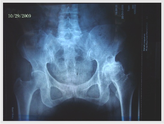
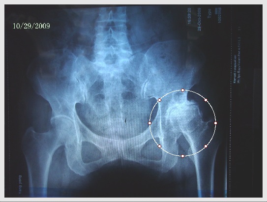
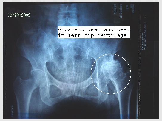
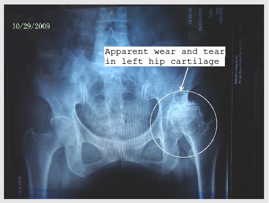
Example 5 Let’s illustrate how to add annotation in an image. In this example,
suppose we need to add some remarks on top of the following X-ray image:
1.
We
begin with inserting the image (See topic 2.17 How to insert an image?):
2.
Insert
a circle to the image the same way as in Example 2. Move the circle to a
proper location and change its size to cover the entire area of interest.
Change the color of the circle (if necessary) to make it apparent (e.g.
White):
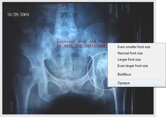
3.
Add
a textbox:
(1)
Insert
a textbox the same way as in Example 3 (5).
(2)
Type
annotation, e.g. “Apparent wear and tear in left hip cartilage”.
(3)
Right
click on border of the textbox to select option “Opaque” from the floating
menu:
(4)
Right
click on border of the textbox to select option “
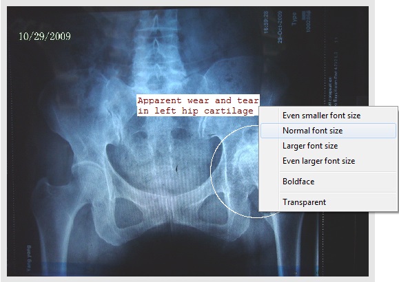
(5)
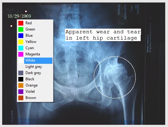
Highlight
the text in textbox and right click to select “Black” from floating menu
“Text colors…”.
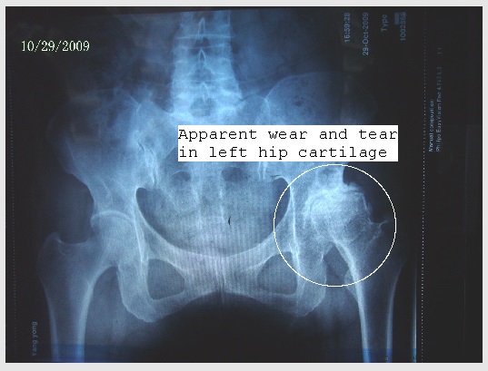
(6)
Move
the textbox to the appropriate location:
![]()
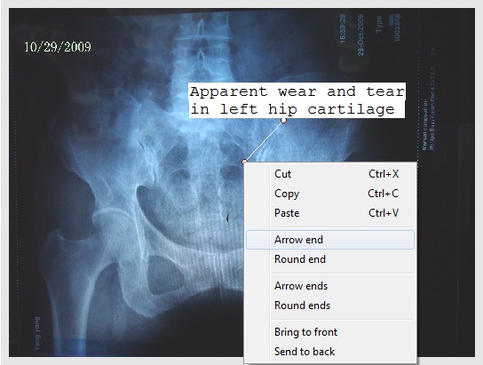
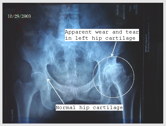
4.
Add
a line with an arrow that points at the circle:
(1)
Click
the “Line type” button ![]() from either
the top or bottom Toolbar to insert a line.
from either
the top or bottom Toolbar to insert a line.
(2)
Change
the line color by selecting color “White” from floating menu “Shape colors…”:
(3)
Move
the line to a proper position near the circle.
(4)
Place
the cursor over the lower control point on the line (the cursor becomes![]() ). Right
click to select “Arrow end” from the floating menu:
). Right
click to select “Arrow end” from the floating menu:
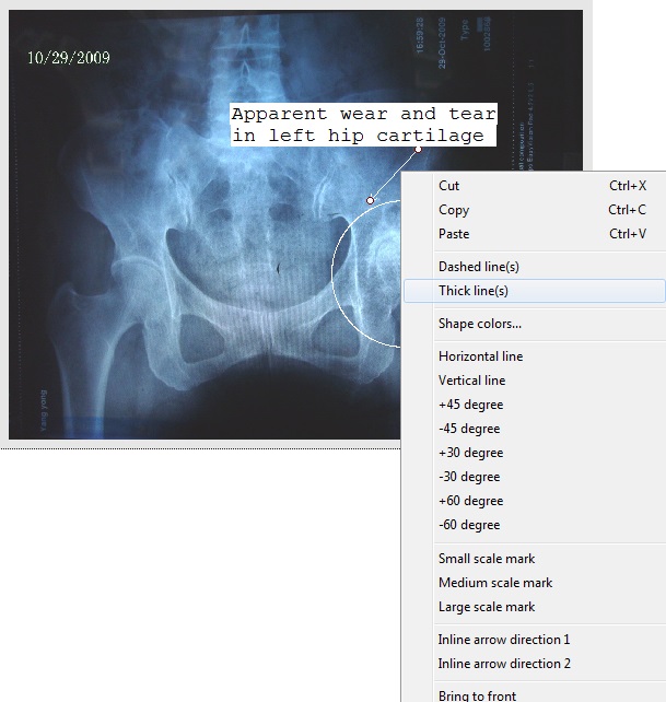
(5)
Place
the cursor over the non-control point on the line (the cursor becomes![]() . Right
click to select “Thick line(s)” from the floating menu:
. Right
click to select “Thick line(s)” from the floating menu:
(6)
Place
the cursor over the lower control point on the line (the cursor becomes![]() ). While
holding down the left button, drag that point until it touches the circle:
). While
holding down the left button, drag that point until it touches the circle:
5.
Add
a second textbox and a second arrow-ended line by the same way:
1.
Click
“View” => “Find” or press shortcut keys Ctrl+F
(or Alt+V, then I) to open “Find” dialog box.
2.
Type
in the text string you want to search.
3.
Make
choice for search scope:
o “From the selected window”
o “From all opened windows”
o “From files” (to search the string
in all files under a specific directory, specified by using “Browse”, without
having to open any file)
4.
Check/uncheck
“Match case” and/or “Match word” if applicable.
5.
Press
“Find Next” or “Find Last” to start searching forward or backwards from your
cursor.
1.
Click
“View” => “Replace” or press shortcut keys Ctrl+H
(or Alt+V, then R) to open “Replace” dialog box.
2.
Type
in the text string to be replaced in the top space.
3.
Type
the text string to be replaced with in the bottom space.
4.
Make
choice for search/replace scope:
5.
Check/uncheck
“Match case” and/or “Match word” if applicable.
6.
Click
“Find Next” and “Replace” to replace string one by one.
7.
Click
“Replace All” to replace all strings within the scope.
TuQuick allows you to insert links in any TuQuick file so that the viewer of the file can jump to a
WEB site or download a TuQuick solution quickly.
Specific methods to do so:
In client software
TuQuick.exe, open and select a TuQuick file which
allows modification, then move the caret to where you want the link to be
inserted in the file. After that, continue with the following steps while
connected to the Internet.
If you want to insert an external WEB link
showing as text:
1.
Type,
or copy/paste the URL address, e.g. http://google.com, into the TuQuick file.
2.
Highlight
the entire URL address, right click to select “Set WEB link”. The URL address
becomes a web link: http://google.com.
If you want to insert an external WEB link
showing as thumbnail image:
1.
Highlight
the image you want make it as thumbnail WEB link.
2.
Right
click to select “Set as thumbnail link”.
3.
In
the next dialog box, type, or copy/paste a URL address and specify thumbnail
image’s size. Then, click OK.
4.
From
then on, the image’s size is reduced (which will make the file smaller too)
and the image is surrounded by a dotted blue frame to indicate “this image is
a link”, like this:  .
.
If you want to insert a link to a TuQuick solution, depending on where the solution, to which you want to make a link,
is from, you can use one of the following methods to insert a link:
Method 1: From a TuQuick.exe’s solution list window. There are three possible ways to do
insert a link:
1.
“Internet”
=> “Check Seeking Status”. In “My Problems Posted” window, double-click on
your problem title (see topic “3.2
How do I know if my problem has solutions?” for detail). Then,
right-click on the solution title of interest, and select “Insert TuQuick link” from the floating menu. The link to the
solution file is inserted into your TuQuick file at
the caret.
2.
“Internet”
=> “Check Provided Status” (see topic “5.2 How to check status and
feedbacks of the solutions I provided?” for detail). Then, right-click on
the solution title of interest, and select “Insert TuQuick
link” from the floating menu. The link to the solution file is inserted into
your TuQuick file at the caret.
3.
“Internet”
=> “Find Problem” . In “Problem Posted by Others”
window, select a problem, right-click to select “Solution Details” (see topic
“4.2 How to find a problem
posted on TuQuick database?” for detail). Then,
right-click on the solution title of interest, and select “Insert TuQuick link” from the floating menu. The link to the
solution file is inserted into your TuQuick file at
the caret.
Method 2: From TuQuick WEB site’s Showcase list. Specifically, use any
WEB browser to enter TuQuick Web sit; then place
mouse at the top menu “Demo”, pull down the menu and select “Problem &
Solution showcase” => Click interested title to open the text part of a
problem; then, in the bottom pane, follow instruction 1 copy link string and
paste into caret position of your TuQuick file.
(Related topic: “6.3 Can I
browse solutions in general without seeking any specific one? ”).
Method 3: From a TuQuick solution file already on your computer. Make sure
the solution file is open and selected in TuQuick
application software. Then, select top menu “View”, then “Links”. Follow the
information displayed at this moment to complete the job.
(Related topic: “6.4 How to let other people
know a good solution?”)
To invoke a link:
While caret is anywhere
inside the link, right click.
·
If
this is a WEB link (in text or in thumbnail image), select “Open WEB link”,
the specified page will launch by your web browser.
·
If
this is a TuQuick link, select “Download problem”
or “Download solution” or “Download hint”, the specified file(s) will then be
downloaded and displayed.
1.
Open
the file you want to check spelling. If only want to check partial text,
highlight the partial text.
2.
Click
“View” => “Spelling” or press shortcut keys Alt+V,
then S to open “Check spelling” dialog box.
3.
To
ignore a misspelled word, click “Ignore”.
4.
To
ignore all instances of a misspelled word, from now on, click “Ignore All”.
5.
To
make change using a suggested word, select the suggested word (and leave
“Your own modified word” empty).
6.
To
make change using your own word, fill your own word in “Your own modified
word”.
7.
To
make change on a misspelled word, click “Change”.
8.
8. To use the same word to change all instances
of a misspelled word from now on, click “Change All”.
Please note:
To import content from a
PDF file to your TuQuick file, first move the caret
to where you want the content to be inserted, click menu “Edit” => “Import
PDF” (or to press shortcut keys Alt+E, then D) to
select the file you want to import content from. In the dialog window “Import
from PDF file”, specify page(s) and method of import:
Please note:
To import content from a
LaTeX file to your TuQuick
file, first move the caret to where you want the content to be inserted,
click menu “Edit” => “Import LaTeX” (or to press
shortcut keys Alt+E, then X) to select the *.tex file you want to import content from.
In addition to the main LaTeX *.tex file, if needed and
you want, the following files associated with the main LaTeX
file should also be at their correct locations:
The import process will
check these files to extract useful information if they are available.
Because of almost
infinitely many extensions of LaTeX, it is expected
that some content in some extensions may not be perfectly imported. In this
sense, this functional feature is experimental in nature.
You can attach any kind
of file into a TuQuick file, to become a part of
the TuQuick file.
To attach a file:
To remove an attached
file:
To view filename and
size of an attached file:
To save an attached
file:
To open an attached
file:
You can user TuQuick’s mirroring function to view two parts of a long
file and edit one of them at the same time:
A separate mirror file
window will open to let you view (and copy) any part of the long file over
there while you can continue view or edit another part of your long file in
its original window. The mirrored file is read-only.
When you modify the
original file, The mirrored file will be automatically updated to the latest
content in your original file.
If you hold down the
Ctrl key while you operate on scroll bar (or hit PgUp/PgDn
key) on the original file, the mirrored file will also scroll to the same
position in the same direction. This is particularly helpful when editing a
large table. However, this feature is available only when original file’s
window and mirrored file’s window have exactly the same size, which can be
achieved by using “Window” => “Tile Horizontally/Vertically” menu.
There are two approaches
to seek solutions for your problem:
|
Approach |
Post the whole problem
online |
Enter a few keywords (up to 1000 characters) of the problem |
|
Advantage |
·
More
likely to find more accurate solutions; ·
May
have new solutions arrive later specifically for your problem. |
·
Don’t
need to enter the whole problem (although for copy/paste it doesn’t matter) |
|
Disadvantage |
·
Need
to take time to enter the whole problem (although for copy/paste it doesn’t
matter) |
·
Solutions
found may not be accurately for your problem; ·
No
opportunity to let someone to provide solution specifically for your
problem. |
Step 1: Make
sure that one problem file is opened and selected. According to the approach
you decide to use for seeking solutions, this file should contain the whole
problem content, or some keywords.
Step 2: Click
menu “Internet” => “Seek solution” (or press shortcut keys Alt+I, then E). A new window “Seek Solution” will pop up.
Make sure the file name is correct.
Step 3: Select
options to seek solutions:
o Click “Post it to all TuQuick users”, or
o Click “Post it to the listed TuQuick users” to post your problem only to listed TuQuick users. In this case, you need to enter these user
IDs in the right-side window (one ID per line). You can also click “Grouping”
button open a Grouping dialog box, where you can add, switch or delete
groups, then click OK to confirm and save. (Each time when the “Seek
Solution” window is opened, it will automatically fill the option and user
IDs you entered last time.)
o Click “Search from all TuQuick users”, or
o Click “Search from the listed TuQuick users”.
Step 4: Press
“Seek” to post your problem. A new window “Uploading” will pop up to show the
uploading status.
Why would I need to post my problem only to
selected providers?
You may do so if you
want to limit posting your problem to certain solution providers, e.g. those
you like the most. To find user ID of a solution provider you like, you can
either 1) Click menu “Internet” => “Check Seeking Status” to open a new
window “My Problems Posted”. Right-click on a solution to select “Solution
Details” or double-click on the solution; or 2) Click menu “View” => “File
Attribute” from a solution file window after the file is downloaded.
Notice: Any posted file
may be deleted from server’s database anytime due to its inactivity or other
reasons. Therefore, you always need to keep a copy of any of your files.
For keyword search
approach, a “Keyword … -
Relevant Solutions” window will open automatically, listing solutions found.
For whole-problem
posting approach, you can check
the status of your posted problems any time by clicking menu “Internet” =>
“Check Seeking Status”. This menu item is available when your computer is
connected to the Internet and you have at least one problem posted.
In the "My Problems
Posted" window, column "Solutions" tells you how many
solutions relevant to your problem are available; and column
"Relevancies" lists scores of three solutions most relevant to your
problem, with 100 being the most relevant and 1 being the least relevant.
If the content of the "My Problems Posted" window has been changed since you viewed the status last time, TuQuick will remind you to check the latest change by placing a * sign at the end of a relevant menu.
You can select and
download solutions from "My Problem Posted" window, as long as there
is at least one relevant solution available (under "Solutions"
column) to your problem (See topic “3.2 How do I
know if my problem has solutions?”).
To select a solution:
In "My Problem
Posted" window, double-click on the problem title (or right-click and
select "Solution Details") to open “Relevant solutions"
window. Then choose a solution from the list based on the following
information (Up to 10 most relevant problem files are given in the “Relevant
solutions" window):
In order to make a
selection, you may just first download a relevant problem (or with hint) to
make sure that this is the problem for which you are looking for a solution.
To do this, just double-click on each row. You can also right-click on any
row and select “Download all problems”, to quickly review all problems for
the solutions listed in “Relevant solutions" window.
To download the hint:
If a hint is available
with the solution you selected, you may download the hint (and the problem)
by right-clicking interested row in “Relevant solutions" window and
select “Download hint”. Downloading hint (and problem) is always free.
To download the solution:
Right-click on your
selected problem and select “Download solution”.
All downloaded files are
“Read-only”. Filenames are prefixed by provider’s user ID. You may save your
downloaded files in the usual way. (You will be prompted to do so when
closing the downloaded solution file.) Note: It is not allowed for anyone to
download their own solutions.
There are two ways you
can give feedback on a solution to the solution provider:
To rate a solution:
While connected to
Internet, open and select the solution file you want to rate. Click
“Internet” => “Rate Solution” (or press shortcut keys Alt+I,
then R). Chose your rating score and click “OK”.
You may rate each
downloaded solution only once. To check whether or not you have rated a
solution and what you have rated, click “View” => “File Attribute” (or
press shortcut keys Alt+V, then F) for the selected
solution file.
To write and send a feedback message:
Open window "My
Problem Posted" by clicking menu “Internet” => “Check Seeking
Status”. Highlight one or multiple problems that you wish to remove. Hit
“Delete” key (or right click to select floating menu “Delete”) and confirm
when prompted.
Please note:
For each solution you
provide, TuQuick requires you also post the problem
your solution is for at the same time.
You can find such a
problem from any source (as long as no copyright is violated). One such a
source is TuQuick database (See topic “4.2 How to find a problem posted
on TuQuick database?”), where other TuQuick users post their problems seeking for solutions.
You can even create your own problems to solve.
For how to provide a
solution, see topic “5.1 How
to provide my solution to solution seekers?”
Step 1: Open
"Find Problem Options" window by clicking menu “Internet” =>
“Find Problem” (or pressing shortcut keys Alt+I,
then M).
Step 2:
Step 3: Click
“Continue”. A new window “Problems Posted by Others” opens up. Each item is a
posted problem with following attributes:
Notice: If your select “Only
specialties related to my already posted solution” in the last step, then,
clicking “Continue” will first bring you a list of your posted solutions. You
need to select a solution from the list and right click to select “Find
Related Problems” to get “Problems Posted by Others” window.
Step 4: Select
a problem you are interested in. Right-click and select “Download problem”,
or double-click to download it.
Note:
Hint: Consider
providing solutions to the most recent problem and/or to problems with none
or lower relevance scores.
Step 1 Make sure that:
1)
there
is only one problem file opened (the problem your solution is for, if no or
more than one problem is open, the menu “Internet” “Provide Solution” will be
grayed out);
2)
optionally,
there is only one hint file opened if you have hint for this solution (if more
than one hint file is open, the menu “Internet” “Provide Solution” will be
grayed out);
3)
the solution file you want to provide is opened and highlighted, and
the file’s author must be the current user.
Step 2 Click menu “Internet” => “Provide solution”
(or press shortcut keys Alt+I, then P). A new
window “Provide Solution” will pop up. Make sure that names of all the files
are correct.
Step 3 Select one of the three charge types:
·
“for
free”
·
“with
sharing of advertisement revenue”
·
“with per-download fee required” (Enter fee in specified
currency.)
Step 4 Select one of the two options to provide your
solution:
·
Click
“Post it to all TuQuick users”, or
Step 5 Check box “To my best knowledge, providing this
solution does not violate any Copyright” and then press “Provide”. A new
window “Uploading” will pop up to show the uploading status.
Why need to provide a solution to
selected users only? You may
want to limit your solution to certain solution seekers, e.g. students in
your class. A seeker’s user ID may be found by “Internet” => “Find
Problem” (See topic “4.2 How
to find a problem posted on TuQuick database?”);
or by “View” => “File Attribute” (Similar to topic “3.1 How to post my problem or
enter keywords to seek solutions?”).
How to remove a solution I posted?
Notice:
Any posted file may be deleted from server’s database anytime due to its
inactivity or other reasons. Therefore, owner of the file must keep its copy.
In principle, you can do
whatever you want. TuQuick does not provide any
further facility about it. As examples:
TuQuick fully believes that the solution you provided is
a result of your effort in finding it and writing it into good quality
document. It is your intellectual property you are entitled to own and
therefore should be protected.
First all, TuQuick allows you, as a solution provider, to get some
reward, including financial one, from people who view your solutions.
Secondly, TuQuick tries by technical means to prevent people from
doing following things, after downloading your solution:
Thirdly, TuQuick allows you to delete or update your solutions at
any time.
In addition to
exchanging problems and solutions, you can also exchange messages with any
content between TuQuick users by sending and
receiving feedback messages. This mechanism is similar to email.
To send a feedback
message:
When you create a new *.fbak file, if you have a downloaded solution file open
and selected, then the new *.fbak file will be
automatically pre-filled with the solution content, assigned with the same
filename as the solution file but with extension “.fbak”.
and allowed to be sent only to the solution
provider. Content in this kind of
special feedback file can only be copied/pasted within the same file, and can
not be pasted to another file.
To receive feedback
messages:
To view messages sent
by you:
TuQuick can help you do your teaching routine with great
efficiency. For example, you can use TuQuick as
your homework system at no cost.
You are a good student
with strong self-learning ability, yet, TuQuick can still help you in many ways. For example:
If someday you become
interested in sharing your learning with other people, your familiarity with TuQuick system and these files can help you quickly
accomplish that.
Yes. Although this is
not a main usage model in TuQuick platform, you can
download solutions without uploading your problems:
If you find a good
solution and you want your friends to know this solution, you can do so by
these steps.
You can not change your
username. If you abandon your current username and start to use a new
username, you will not be able to open any file you created under your old
username. Therefore, you probably want to think through when choosing a
username.
You can change your
password by signing in Tuquick web site, and then
clicking the menu “Change Your Password”.
We strongly recommend
that you use the free service “Support”=>“Protect Your Password” from www.tuquick.com WEB site, which will allow
you to reset your password in the event you forgot your password. Otherwise,
there is no way we can help you to reset your password.
Sharing TuQuick files with someone without using TuQuick server is inconvenient and will lose a lot of
benefits of TuQuick system. But it is possible and
useful under certain circumstances (e.g. when connection to TuQuick server is unavailable while you need to let
another person view your document immediately).
To share your TuQuick file with another TuQuick
user (e.g. TuQuick username “John Doe”) without
using TuQuick server:
Now you can pass this
file to that person in whatever way you like (e.g. attachment of email). That
person will be able to open the file and view it on his/her TuQuick client. If the shared file is a problem file,
that person will also be able to copy content from that file (content of a
solution file or a hint file cannot be copied).
TuQuick mobile version (e.g. Android version) is
basically the same as Windows version. Here is the general equivalency
mapping between mouse operation in Windows and touch operation in a mobile
device.
|
Windows moose operation |
Mobile touch operation |
|
Left single click |
Single short touch |
|
Left double click |
Double short touch |
|
Left triple click |
Triple short touch |
|
Right single click |
Single long touch |
|
Scroll by moving
scrolling bar |
Single swipe |
|
Drag move |
Long press then slide |
|
Change display size by
Ctrl+/- |
Pinch touchscreen to zoom |
However, some operation
on a touch screen needs to be somewhat different as described below.
In
addition to mobile system keyboard (software or hardware based), TuQuick provides some extra control keys (Esc, Ctrl, Alt,
Home, End, Delete,… etc.). These extra control keys
are required to use TuQuick client side program.
They are either missing or not functioning correctly on a typical mobile
device keyboard.
The
following table summarizes the major differences between the two modes:
|
Characteristics |
Finger mode |
Mouse mode |
|
A cursor on screen? |
No. |
Yes, always. |
|
Precision of pointing
operation? |
Low. |
High. |
|
Convenience? |
Simple, quick. |
Two steps generally
required: “Move” + “Click” |
|
Visibility of area
being operated on? |
Poor. Finger blocks
the view. |
Very good. |
|
What does one finger
clicking do? |
Click where the finger
is. |
Click where the cursor
is. |
|
What does one finger
swiping do? |
Scroll content where finger
is to display. |
Move cursor position
around displayed content. If content is scrollable, the content (together
with cursor) will be automatically scrolled towards center area of the
screen. |
|
Working with soft
keyboard on touch screen? |
Yes. Whenever soft
keyboard occurs, finger mode is automatically activated. |
No. Whenever soft
keyboard occurs, mouse mode is automatically inactivated. |
|
To be continued... |
|
|
|
|
|
|
TuQuick mobile version is still under development and will
become available soon.